|
|
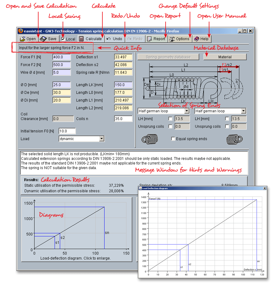
Please login with your username and your password. Select the module ‘Tension spring’ through the tree structure of the project manager by double-clicking on the module or clicking on the button ‘New calculation’.
Spring is a mechanical device designed to store elastic energy when deflected and to return the energy when relaxed. The tension spring offers resistance to an axial force tending to extend its length, with or without initial tension.
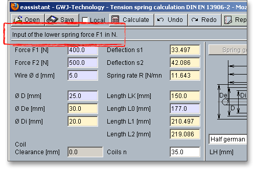
The calculation of the tension spring is based on DIN EN-13906-2. Forces and deflection or a combination of both parameters can be defined for the calculation. The depending values will be automatically calculated.
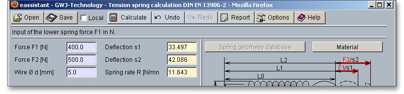
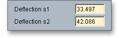
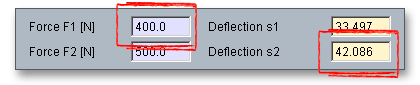
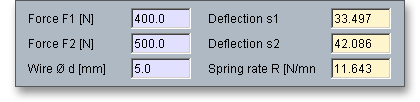
For the entry of forces and deflections there are the following possibilities:
|
|
||
|
|
||
|
|
||
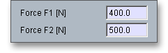
The input fields that are dependent upon one another are color-coded to simplify the connection of force, deflection and length. Click the input field and the corresponding input field will turn yellow. It makes it easier for you to see how these values relate to each other and how they change.
Enter either a value for the wire diameter  or the spring rate
  . Both values will be determined
automatically.
. Both values will be determined
automatically.
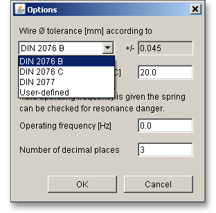
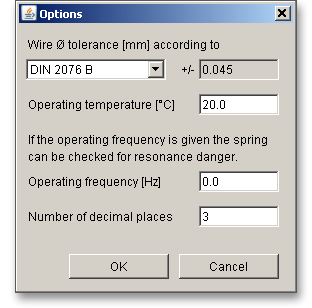
Please Note: If you click the ‘Options’ button, then you can consider the tolerances. Select DIN 2076 B/C or DIN 2077 from the listbox.
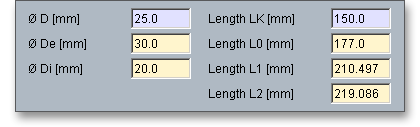
Enter the values for the tension spring geometry (e.g., length, diameter and coils). According to the specified input values, the values are determined automatically.
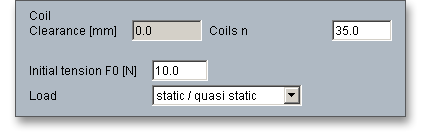
Coils can be wound so tightly that a load is needed to separate the coils. This is an internal load that holds the coils tightly together and this is what is known as initial tension. The initial tension is introduced by winding the coils so that they exert a certain pressure against each other.
The initial tension depends upon the spring material, the diameter of the wire  , the spring index
(coil ratio)
, the spring index
(coil ratio)  and the manufacturing method. In addition, the initial tension depends also on the
maximum permissible shear stress
and the manufacturing method. In addition, the initial tension depends also on the
maximum permissible shear stress  . Hot coiled tension springs are manufactured without initial
tension and are produced with a distance between the adjacent spring coils. Tension springs with
initial tension force have their coils pressed tightly together. Loosely wound springs always have a
small amount of initial tension since it is not possible to achieve uniformly tension-free coiling. A
small amount of initial tension force shall be accepted. Enter the number of coils
. Hot coiled tension springs are manufactured without initial
tension and are produced with a distance between the adjacent spring coils. Tension springs with
initial tension force have their coils pressed tightly together. Loosely wound springs always have a
small amount of initial tension since it is not possible to achieve uniformly tension-free coiling. A
small amount of initial tension force shall be accepted. Enter the number of coils  into the input
field.
into the input
field.
Hot coiled tension springs cannot be made with initial tension force. The heat treatment applied causes gaps to occur between the coils. The size of the gap depends upon the spring index and the degree of torsional stress involved. The following reference values for hot coiled spring up to 25 mm bar diameter can be used:
 0,5 to 5 mm corresponding to a permissible shear stress
 400
400  to 600
  (for spring force
  ).
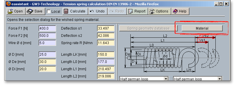
).Please note: Clicking the ‘Material’ button opens the material database. Here you can select different materials.
Futhermore, you get information on the manufacturing process (see also section 15.4 ‘Material
Selection’).
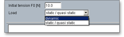
Before starting the calculation, it should be specified whether they will be subjected to static loading, quasi-static loading or dynamic loading. The calculation is possible for both dynamic and static/quasi-static loading. A static loading is:
Quasi-static loading is:
 fatigue strength)

In the case of tension spring dynamic loading is loading variable with time with a number of load cycles over
 and torsional stress range greater than 0,1
  fatigue strength at:
Depending on the required number of cycles  up to rupture it is necessary to differentiate between two
cases as follows:
up to rupture it is necessary to differentiate between two
cases as follows:
 for cold coiled springs: Torsional stress range is lower than the infinite life fatigue limit
 for cold coiled springs: Torsional stress range is greater than the infinite life fatigue limit
but smaller than the low cycle fatigue limit
for cold coiled springs: Torsional stress range is greater than the infinite life fatigue limit
but smaller than the low cycle fatigue limit
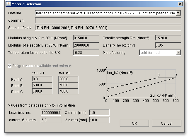
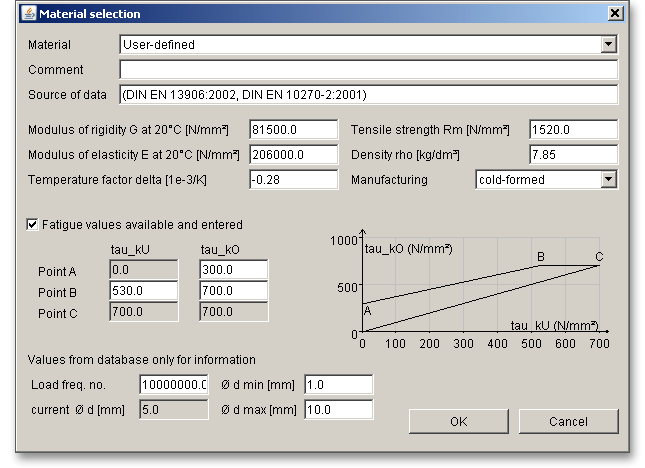
Clicking the button ‘Material’ opens the material database. In case there is no material that will fulfill the design requirements, then simply define your individual material.
Please select the material from the list. You will get detailed information on the material. The two cursor keys ‘Up’ and ‘Down’ of your keyboard allows you to navigate through the material database, so you can compare the different material properties with each other.
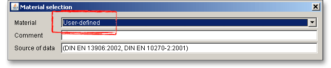
In case you cannot find the material you are looking for in our extensive database, simply define your individual material. You will find the entry ‘User-defined’ in the listbox. If you select this option, the input fields will be enabled, so that you can enter your own input values or add a comment.
In order to confirm your inputs, click the button ‘OK’. Please be advised that changing the material will delete your defined inputs and you have to enter the inputs again.
Depending on the manufacturing process (e.g., hot rolled or cold coiled springs), the calculation of the
tolerances is determined according to DIN 2095 or DIN 2096. In addition, the eigenfrequency of the spring is
calculated.
Please note: The ‘Spring geometry database’ button is disabled because there is no DIN standard that provides
geometry data for the tension spring. In case you need geometry data, it is advisable to seek manufacturers
advise.
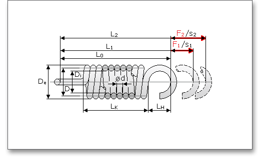
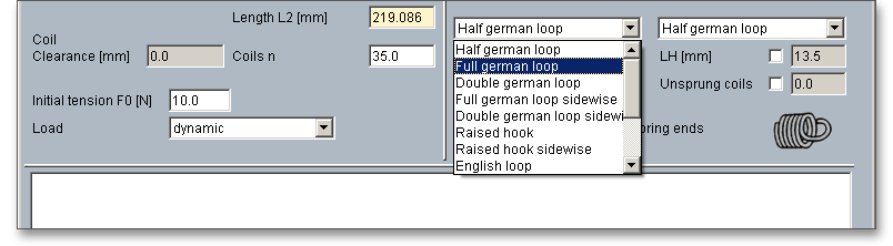
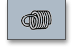
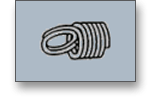
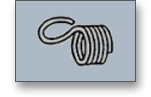
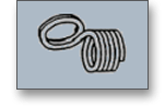
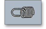
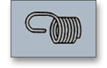
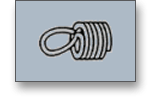
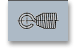
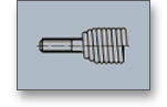
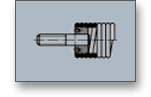
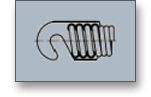
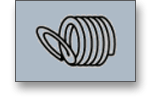
Various forms of loops and connection elements are used for the spring power transmission. Select the spring end types from the list:
|
|
||
|
|
||
|
|
||
|
|
||
|
|
||
|
|
||
|
|
||
|
|
||
|
|
||
|
|
||
|
|
||
|
|
||
|
|
||
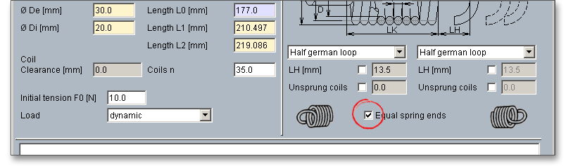
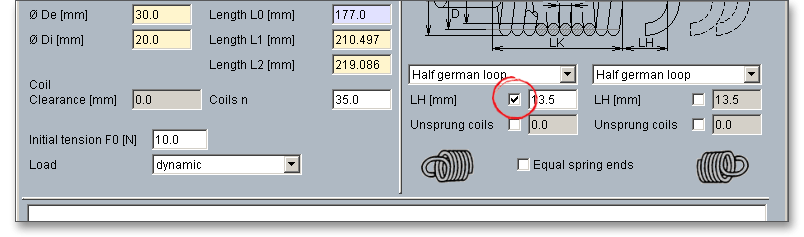
Every spring end can get different loop forms or connection elements. In order to quickly select the same spring end, enable the option ‘Equal spring ends’. If this option remains enabled, the listbox will display always the same spring ends.
The distance  from the inner radius of loop to the spring body is displayed as well as the unsprung coils.
But you can also define your own distance in order to calculate non-standard tension springs. You can enable
the input field by clicking the checkbox next to it. After clicking the checkbox, you have to enter the input
value.
from the inner radius of loop to the spring body is displayed as well as the unsprung coils.
But you can also define your own distance in order to calculate non-standard tension springs. You can enable
the input field by clicking the checkbox next to it. After clicking the checkbox, you have to enter the input
value.
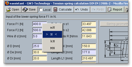
Use this function if you want to change the unit of measurement quickly. Just a right-click on the input field where you want to change the unit. The context menu contains all available units. The two arrows mark the current setting. As soon as you select a unit, the current field value will be converted automatically into the chosen unit of measurement.
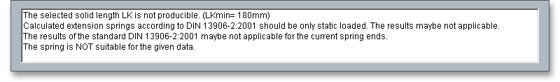
The calculation module provides a message window. This message window displays detailed information, helpful hints or warnings about problems. One of the main benefits of the program is that the software provides suggestions for correcting errors during the data input. If you check the message window carefully for any errors or warnings and follow the hints, you are able to find a solution to quickly resolve calculation problems.
The quick info feature gives you additional information about all input fields and buttons. Move the mouse pointer to an input field or a button, then you will get some additional information. This information will be displayed in the quick info line.
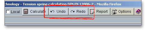
The button ‘Undo’ allows you to reset your input to an older state. The button ‘Redo’ reverses the undo.
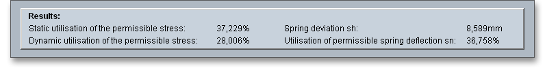
All important calculation results, such as the static and dynamic utilization of the permissable stress, the spring
deviation  and the utilization of the permissable spring deflection
  , will be calculated during every input
and will be displayed in the result panel. A recalculation occurs after every data input. Any changes
that are made to the user interface take effect immediately. Press the Enter key or move to the
next input field to complete the input. Alternatively, use the Tab key to jump from field to field or
click the ‘Calculate’ button after every input. Your entries will be also confirmed and the calculation
results will displayed automatically. If the result exceeds certain values, the result will be marked
red.
, will be calculated during every input
and will be displayed in the result panel. A recalculation occurs after every data input. Any changes
that are made to the user interface take effect immediately. Press the Enter key or move to the
next input field to complete the input. Alternatively, use the Tab key to jump from field to field or
click the ‘Calculate’ button after every input. Your entries will be also confirmed and the calculation
results will displayed automatically. If the result exceeds certain values, the result will be marked
red.
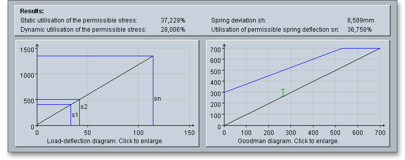
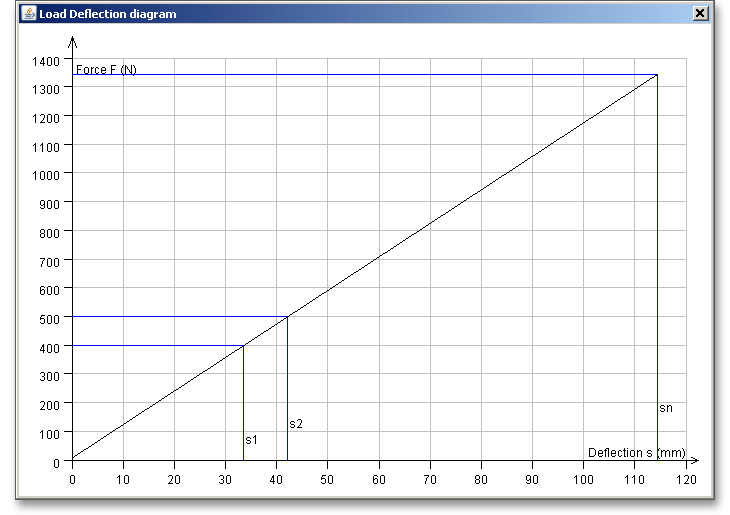
In addition to the calculation results, a graphical representation of the load-deflection and Godman diagram is available. The Goodman diagram is displayed only for the dynamic load.
Click directly on the diagram to open the diagram in a new window and to increase the size of the diagram.
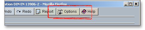
After the completion of your calculation, you can create a calculation report. Click on the ‘Report’ button.
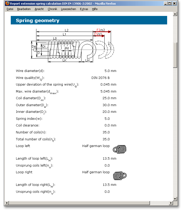
You can navigate through the report via the table of contents that provides links to the input values, results and figures. This calculation report contains all input data, the calculation method as well as all detailed results. The report is available in HTML and PDF format. The calculation report saved in HTML format, can be opened in a web browser or in Word for Windows.
You may also print or save the calculation report:
 ‘Save as’ from your browser menu
bar. Select the file type ‘Webpage complete’, then just click on the button ‘Save’.
‘Save as’ from your browser menu
bar. Select the file type ‘Webpage complete’, then just click on the button ‘Save’.
When the calculation is finished, you can save it to your computer or to the eAssistant server. Click on the button ‘Save’.
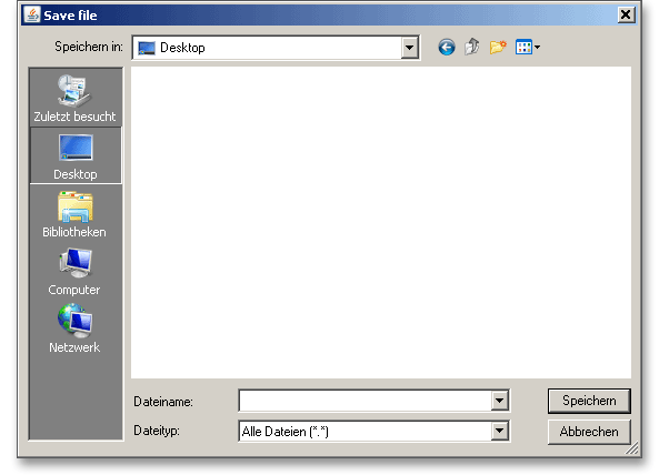
Before you can save the calculation to your computer, you need to activate the checkbox ‘Enable save data local’ in the project manager and the option ‘Local’ in the calculation module. A standard Windows dialog for saving files will appear. Now you will be able to save the calculation to your computer.
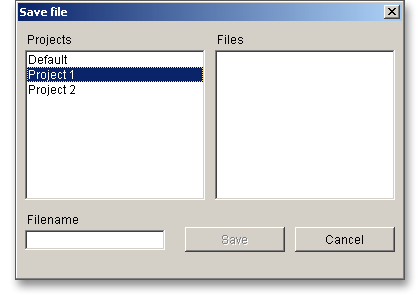
In case you do not activate the option in order to save your files locally, then a new window is opened and you can save the calculation to the eAssistant server. Please enter a name into the input field ‘Filename’ and click on the button ‘Save’. Then click on the button ‘Refresh’ in the project manager. Your saved calculation file is displayed in the window ‘Files’.
Click the button ‘Options’ in order to change the default settings.
Here are the default settings that you can modify: