|
|
A parallel key is a positive shaft-hub-connection. The torque is transmitted from the shaft to the hub via the parallel key. The main purpose of the parallel key is to transmit static and quasi-static torques. The parallel key can be used with limitations also for swelling and alternating torques. In case a good assembly and disassembly of the shaft-hub-connection are required or necessary (e.g., replacement or repair), then a parallel key may be used. A shearing off of the parallel key does not happen very often and occurs only in the event of overloading. The fretting corrosion due to rotating bending and/or torsional oscillation has been proven in numerous endurance tests and is usually the crucial factor which leads to the failure of the shaft-hub-connection.
For the proof of strength of parallel keys, it is necessary to check the following factors:
In DIN 6892 a distinction is made between different methods for the proof of strength for parallel keys: method A, B and C.
This method is an experimental proof of strength under conditions of practice and/or an extensive stress analysis of the entire parallel key connection, consisting of shaft, parallel key and hub.
The dimensioning takes place due to a detailed consideration of the occurring surface pressures. In addition, the proof of strength for the shaft is carried out according to the nominal stress concept.
It is a rough calculation of the surface pressure and resulting estimation of the shaft stress.
The calculation is based on DIN 6892. The DIN standard specifies the following scope:
 C to
C to
 C
C
The geometry of the parallel keys can be selected according to DIN 6885-1, DIN 6885-2 and DIN 6885-3. This geometry selection includes the standard lengths of parallel keys. The supporting length is determined from the standard length and the chosen parallel key type. There are various types of parallel keys - the types A to J are available.
The supporting length  for the different types of parallel keys is calculated as follows:


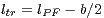
 | is the supporting length |
 | is the standard length |
 | is the width |
For nonstandard parallel keys, it is possible to define an individual parallel key geometry and supporting lengths. The different keyway depths in shaft and hub as well as the chamfer of the parallel key are taken into consideration for the calculation. For method B, the chamfer on the shaft and hub keyway is additionally integrated into the calculation.
If you choose to enter the supporting length manually, the supporting length  of the hub keyway can be
smaller than
of the hub keyway can be
smaller than  of the parallel key. For this case, according to DIN 6892, the length
  of each
extended part may be calculated as carrying up to maximum
of each
extended part may be calculated as carrying up to maximum  . For a safe calculation, the
eAssistant software uses the most conservative case and this exceptional case will not be considered
automatically.
. For a safe calculation, the
eAssistant software uses the most conservative case and this exceptional case will not be considered
automatically.
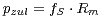
The effective surface pressure between parallel key and shaft or hub keyway wall must not exceed the
permissible value. The permissible values result from the material strength - for ductile materials from the yield
point ( and/or
  ) and for brittle materials from the tensile strength
  . The calculation can be run by
using unusual metallic materials. The following strength criteria have to be fulfilled with the appropriate
safeties:
. The calculation can be run by
using unusual metallic materials. The following strength criteria have to be fulfilled with the appropriate
safeties:
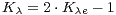
 is the load direction changing factor and
  is the load peak frequency factor. The load direction
changing factor considers the influence of the number of load direction changes on the permissible surface
pressure. The load peak frequency factor evaluates the influence of the load peaks on the maximum surface
pressure.
is the load peak frequency factor. The load direction
changing factor considers the influence of the number of load direction changes on the permissible surface
pressure. The load peak frequency factor evaluates the influence of the load peaks on the maximum surface
pressure.
The calculation method applies for one-sided stress and with restriction for an alternating stress of the parallel keys. The surface pressure is determined from the torque that is transmitted.
The supporting keyway depth between parallel key and shaft as well as hub keyway wall are given by the
following equations. Therefore, a  chamfer and radius on the parallel key as well as on the shaft and hub
keyway edge are considered according to the figure above:
chamfer and radius on the parallel key as well as on the shaft and hub
keyway edge are considered according to the figure above:


according to the specifications in the standard sheets for the respective materials.
 | is the support factor |
 | is the hardness factor |
The application factor  is determined for the calculation of the equivalent torque
  (similar to the gear
calculation according to DIN 3990) with the following table:
(similar to the gear
calculation according to DIN 3990) with the following table:
| Application Factors
 According to DIN 3990-1: 1987-12 According to DIN 3990-1: 1987-12 | ||||
| Working Characteristics | Working Characteristics of the Driven Machine
| |||
| of the Driving Machine | Uniform | Light Shocks | Moderate Shocks | Heavy Shocks |
| Uniform | 1,0 | 1,25 | 1,5 | 1,75 |
| Light Shocks | 1,1 | 1,35 | 1,6 | 1,85 |
| Moderate Shocks | 1,25 | 1,5 | 1,75 | 2,0 |
| Heavy Shocks | 1,5 | 1,75 | 2,0 | 2,25 or higher |
Uniform: e.g., electric motor, steam or gas turbine (small, rarely occurring starting torques)
Light Shocks: e.g., electric motor, steam or gas turbine (large, frequently occurring starting torques)
Moderate Shocks: e.g., multiple cylinder internal combustion engines
Heavy Shocks: e.g., single cylinder internal combustion engines
Uniform: Steady load current generator, uniformly loaded conveyor belt or platform conveyor, worm conveyor,
light lifts, packing machinery, feed drives for machine tools, ventilators, light-weight centrifuges, centrifugal
pumps, agitators and mixers for light liquids or uniform density materials, shears, presses, stamping machines,
vertical gear, running gear
Light Shocks: Non-uniformly (i.e. with piece or batched components) loaded conveyor belts or platform
conveyors, machine-tool main drives, heavy lifts, crane slewing gear, industrial and mine ventilators, heavy
centrifuges, centrifugal pumps, agitators and mixers for viscous liquids or substances of non-uniform density,
multi-cylinder piston pumps, distribution pumps, extruders (general), calendars, rotating kilns, rolling mill stands,
continuous zinc and aluminium strip mills, wire and bar mills
Moderate Shocks: Rubber extruders, continuously operating mixers for rubber and plastics, ball mills (light),
wood-working machines (gang saws, lathes), billet rolling mills, lifting gear, single cylinder piston
pumps
Heavy Shocks: Excavators (bucket wheel drives), bucket chain drives, sieve drives, power shovels, ball mills
(heavy), rubber kneaders, crushers (stone, ore), foundry machines, heavy distribution pumps, rotary
drills, brick presses, de-barking mills, peeling machines, cold strip c, e, briquette presses, breaker
mills
Due to deviation in form and position of a single parallel key, an unbalanced or uneven carrying of two parallel
keys, that are arranged evenly around the circumference, occurs. Thus, the reduced load capacity of the parallel
key is considered by the load factor  . In practice, not more than two parallel keys are used because of the
load distribution that is difficult to determine.
. In practice, not more than two parallel keys are used because of the
load distribution that is difficult to determine.

 ):
): 
 ):
):  for the determination of the equivalent surface pressure,
 for the determination of the maximum surface pressure
Compared to the calculation of the equivalent surface pressure, a higher load part  can be estimated for the
determination of the maximum surface pressure because a torque occurring in several load peaks leads to a
higher load part by deformation on the parallel key and keyway ground. Using these load parts, ductile materials
with pronounced yield point as well as sufficient manufacturing accuracy are required. For brittle materials
(e.g., gray cast iron), there is no established knowledge about the load capacity using two parallel
keys.
can be estimated for the
determination of the maximum surface pressure because a torque occurring in several load peaks leads to a
higher load part by deformation on the parallel key and keyway ground. Using these load parts, ductile materials
with pronounced yield point as well as sufficient manufacturing accuracy are required. For brittle materials
(e.g., gray cast iron), there is no established knowledge about the load capacity using two parallel
keys.
The load distribution factor  takes an uneven load distribution into consideration along the keyway length as
well as the ratio of load in and output. For using two parallel keys, the unbalanced carrying is considered by the
following assumption:
takes an uneven load distribution into consideration along the keyway length as
well as the ratio of load in and output. For using two parallel keys, the unbalanced carrying is considered by the
following assumption:

The factor  is dependent upon the kind of load in and output position. Regardless of the torque flow
direction, three cases are distinguished.
is dependent upon the kind of load in and output position. Regardless of the torque flow
direction, three cases are distinguished.
For a stepped hub, it means (see above figure):
 | Small outer diameter of stepped hub |
 | Large outer diameter of stepped hub |
 | Distance between the axial cutting planes through N and W |
 | Width of the hub with  within the carrying part of the parallel key, i.e., within the carrying part of the parallel key, i.e., 
|
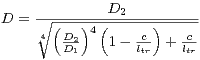
 is the outer diameter of the hub or the outer diameter of the alternative cylinder with equal torsional
stiffness. The alternative outer diameter is calculated as follows:
is the outer diameter of the hub or the outer diameter of the alternative cylinder with equal torsional
stiffness. The alternative outer diameter is calculated as follows:
Depending on  , the factor
  is determined by using the figures 3, 4 and 5 in DIN 6892.
These diagrams are integrated into the calculation module and are valid for a specific ratio
is determined by using the figures 3, 4 and 5 in DIN 6892.
These diagrams are integrated into the calculation module and are valid for a specific ratio 
 . For other ratios
  , the values are determined from two diagrams by
interpolation.
, the values are determined from two diagrams by
interpolation.
For an interference fit, part of the torque is transmitted by friction. The friction factor  considers that. But it is
taken into consideration only for the calculation of the maximum effective surface pressure
considers that. But it is
taken into consideration only for the calculation of the maximum effective surface pressure  . For a
dynamic load, an interference fit stops the occurrence of fretting corrosion. A clearance fit or interference fit
adversely affects the shaft strength. For the determination of the friction factor, a minimum friction
torque
. For a
dynamic load, an interference fit stops the occurrence of fretting corrosion. A clearance fit or interference fit
adversely affects the shaft strength. For the determination of the friction factor, a minimum friction
torque  of the interference fit is assumed. According to DIN 7190, this can be obtained for a
hole without keyway. The joint pressure, that is reduced due to the parallel key in comparison to
the hole without keyway, is considered by the factor
of the interference fit is assumed. According to DIN 7190, this can be obtained for a
hole without keyway. The joint pressure, that is reduced due to the parallel key in comparison to
the hole without keyway, is considered by the factor  . Thus, the friction torque, effective for the
power transmission, is decreased. As a first approximation,
. Thus, the friction torque, effective for the
power transmission, is decreased. As a first approximation,  can be specified for a parallel
key.
can be specified for a parallel
key.
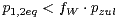
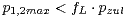
With the maximum load peak torque  , occurring during the entire operation time, it applies:
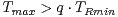
For  the load peak torque is transmitted by friction. In this case, the surface pressure,
occurring in the parallel key, is not relevant. A check of the maximum surface pressure
the load peak torque is transmitted by friction. In this case, the surface pressure,
occurring in the parallel key, is not relevant. A check of the maximum surface pressure  is not necessary
according to DIN 6892. However, it is integrated into the calculation.
is not necessary
according to DIN 6892. However, it is integrated into the calculation.
Please note: For brittle materials (e.g., gray cast iron), no interference fit is allowed.
Parallel key connections are only conditionally usable during changing the direction of torque. However, the
rating life is limited if it comes to constant slipping between shaft and hub and thus to a deflection of the parallel
key connection. There are two different cases:
Case 1: One-sided load of the parallel key during alternating load direction. The maximum torques in reverse direction (against the main load direction) do not exceed the effective part of the minimum friction torque.

Case 2: Alternating load of the parallel key during alternating load direction. The maximum torques exceed the effective part of the minimum friction torque in both directions.

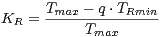
In case 2, the changes of load direction factor  is dependent upon the frequency
  of changes of load
direction for the parallel key. It can be determined according to DIN 6892, figure 6. Two cases are
distinguished:
of changes of load
direction for the parallel key. It can be determined according to DIN 6892, figure 6. Two cases are
distinguished:
Load direction changes, that occur due to special cases, have to be considered as well.
Load peaks occur when the torque clearly exceeds the equivalent torque  . Special cases may occur due to
starting impacts, short-circuit torques, emergency breaking torques, abrupt blockings etc. The frequency
. Special cases may occur due to
starting impacts, short-circuit torques, emergency breaking torques, abrupt blockings etc. The frequency  of the load peaks has to be estimated during the entire operating time. For a single load peak, depending on the
ductility of the material, the 1,3 to 1,5 times the permanent surface pressure is allowed. The progress
of
of the load peaks has to be estimated during the entire operating time. For a single load peak, depending on the
ductility of the material, the 1,3 to 1,5 times the permanent surface pressure is allowed. The progress
of  for ductile and brittle materials over the frequency is shown in figure 5 according to DIN
6892.
for ductile and brittle materials over the frequency is shown in figure 5 according to DIN
6892.
Using the support factor  , a supporting effect can be considered that occurs for compressive stress
components. From experience, the supporting effect for hubs is larger due to the higher stressed
material volume than for shafts and parallel keys (see table: support and hardness factors for different
materials).
, a supporting effect can be considered that occurs for compressive stress
components. From experience, the supporting effect for hubs is larger due to the higher stressed
material volume than for shafts and parallel keys (see table: support and hardness factors for different
materials).
The hardness influence factor  is determined from the ratio of surface strength to core strength for
case-hardened components. By the hardness influence factor, an increasing of the permissible surface pressure
is considered (see table: support and hardness factors for different materials).
is determined from the ratio of surface strength to core strength for
case-hardened components. By the hardness influence factor, an increasing of the permissible surface pressure
is considered (see table: support and hardness factors for different materials).
| Support and Hardness Influence Factors for Different Materials
| |||
| Component | Material |  |  |
| Parallel key | Structural steel according to DIN EN 10 025 | 1,0 | 1,0 |
| Bright steel according to DIN 1652-4 | 1,0 | 1,0 | |
| Heat-treated steel according to DIN EN 10 083-1 and 10 083-2 | 1,0 | 1,0 | |
| Case-hardened steel according to DIN 17210 | 1,0 | 1,15 | |
| Shaft | Structural steel according to DIN EN 10 025 | 1,2 | 1,0 |
| Heat-treated steel according to DIN EN 10 083-1 and 10 083-2 | 1,2 | 1,0 | |
| Case-hardened steel according to DIN 17 210 | 1,2 | 1,15 | |
| Gray cast iron with lamellar graphite according to DIN 1693-1 and 1693-2 | 1,2 | 1,0 | |
| Steel casting according to DIN 1681 | 1,2 | 1,0 | |
| Gray cast iron with lamellar graphite according to DIN 1691 | 1,0 | - | |
| Hub | Structural steel according to DIN EN 10 025 | 1,5 | 1,0 |
| Heat-treated steel according to DIN EN 10 083-1 and 10 083-2 | 1,5 | 1,0 | |
| Case-hardened steel according to DIN EN 17 210 | 1,5 | 1,15 | |
| Gray cast iron with spheroidal graphite according to DIN 1693-1 and 1693-2 | 1,5 | 1,0 | |
| Steel casting according to DIN 1681 | 1,5 | 1,0 | |
| Gray cast iron with lamellar graphite according to DIN 1691 | 2,0 | - | |
The calculation method B provides a more precise way to determine the surface pressure. The strength of the shaft is verified according to the nominal stress concept. Select method B from the listbox. The calculation method B requires some additional inputs. Click the button ‘Input data method B’.
A new window is opened.
The following input can be defined:


 of hub with
  within
 between load in and output position
The calculation method C according to DIN 6892 is suitable only for a rough calculation of parallel keys. The method is based on the following simplifications:
 ; a length going beyond it does not make a considerable contribution for the torque
transmission.
; a length going beyond it does not make a considerable contribution for the torque
transmission.

The button for the dimensioning functions is marked by a calculator symbol and is located next to the input fields. If you click on the dimensioning buttons, you get a suggestion for an appropriate input value. The calculation of the value is carried out so that the given minimum safety is fulfilled. The default value for the minimum safety is set to ‘1.2’. Clicking the button ‘Options’ allows you to change this value. The following dimensioning functions (calculator button) provide you with optimal support:
|
|
||
|
|
||
|
|
||
|
|
||
|
|
||
Clicking the button ‘Material’ opens the material database. In case there is no material that will fulfill the design requirements, then simply define your individual material.
You will find the entry ‘User-defined’ in the listbox. If you select this option, the input fields will be enabled, so that you can enter your own input values or add a comment. Please select the material from the list. You will get detailed information on the material. The two cursor keys ‘Up’ and ‘Down’ of your keyboard allows you to navigate through the material database, so you can compare the different material properties with each other. That applies for shaft, hub and parallel key.
Click the button ‘Parallel key’ in order to select parallel keys quickly and easily.
The geometry database will be opended. The database allows you to select a parallel key.
The database provides the parallel key selection according to DIN 6885 sheet 1 to 3. The parallel key forms A to
J as well as the parallel key size, including the lengths, can be selected. Clicking the button ‘OK’ confirms yur
inputs and leads you back to the the main mask.
The geometry database offers the possibility to calculate individual parallel keys. You can define the geometry of parallel keys as you wish and different from the DIN standard. The parallel key forms from A to J are also available. In order to define your individual parallel key, click the button ‘Parallel key’ to open the parallel key database. Enable the option ‘Own input’ and choose the suitable dimensions from the list or enter your own values directly into the input field.
It is possible to define a supporting length for your individual parallel key. Select ‘User defined input’ from the listbox and enter your own value for the supporting length.
You can specify different supporting length for the shaft and hub. Place a checkmark in order to enable the input field and enter a value for the supporting length.
Use this function if you want to change the unit of measurement quickly. Just a right-click on the input field where you want to change the unit. The context menu contains all available units. The two arrows mark the current setting. As soon as you select a unit, the current field value will be converted automatically into the chosen unit of measurement.
The button ‘Undo’ allows you to reset your input to an older state. The button ‘Redo’ reverses the undo.
The calculation module provides a message window. This message window displays detailed information, helpful hints or warnings about problems. One of the main benefits of the program is that the software provides suggestions for correcting errors during the data input. If you check the message window carefully for any errors or warnings and follow the hints, you are able to find a solution to quickly resolve calculation problems.
The quick info feature gives you additional information about all input fields and buttons. Move the mouse pointer to an input field or a button, then you will get some additional information. This information will be displayed in the quick info line.
All important calculation results, such as the safeties for the operation load or at the maximum load for all three components (shaft, hub and parallel key) or the equivalent pressure will be calculated during every input and will be displayed in the result panel. A recalculation occurs after every data input. Any changes that are made to the user interface take effect immediately. Press the Enter key or move to the next input field to complete the input. Alternatively, use the Tab key to jump from field to field or click the ‘Calculate’ button after every input. Your entries will be also confirmed and the calculation results will displayed automatically. If the result exceeds certain values, the result will be marked red.
After the completion of your calculation, you can create a calculation report. Click on the ‘Report’ button.
You can navigate through the report via the table of contents that provides links to the input values, results and figures. This calculation report contains all input data, the calculation method as well as all detailed results. The report is available in HTML and PDF format. The calculation report saved in HTML format, can be opened in a web browser or in Word for Windows. You may also print or save the calculation report:
 ‘Save as’ from your browser menu
bar. Select the file type ‘Webpage complete’, then just click on the button ‘Save’.
‘Save as’ from your browser menu
bar. Select the file type ‘Webpage complete’, then just click on the button ‘Save’.
When the calculation is finished, you can save it to your computer or to the eAssistant server. Click on the button ‘Save’.
Before you can save the calculation to your computer, you need to activate the checkbox ‘Enable save data local’ in the project manager and the option ‘Local’ in the calculation module. A standard Windows dialog for saving files will appear. Now you will be able to save the calculation to your computer.
In case you do not activate the option in order to save your files locally, then a new window is opened and you can save the calculation to the eAssistant server. Please enter a name into the input field ‘Filename’ and click on the button ‘Save’. Then click on the button ‘Refresh’ in the project manager. Your saved calculation file is displayed in the window ‘Files’.
Click the button ‘Options’ in order to change the default settings.
The button ‘Options’ allows you to define the minimum safeties. Additionally, there is the possibility to enter the number of decimal places for the output of the numerical values in the report.
Please login with your username and your password. Select the module ‘Parallel key’ through the tree
structure of the project manager by double-clicking on the module or clicking on the button ‘New
calculation’.
A strength calculation for the following shaft-hub-connection is required (see also DIN 6892, Example E.2). Enter the following values into the input fields:
| Shaft diameter | = 60 mm |
| Application factor | = 1.75 |
Outer diameter hub  | = 120 mm |
| Calculation method | = B |
Operation nominal torque  | = 1.950 Nm |
Min. frictional torque  | = 1.250 Nm |
Max. load peak torque  | = 3.900 Nm |
Load peaks  | = 500 |
| Material shaft | = C45 hardened and tempered |
| Material hub | = 34CrNiMo6 hardened and tempered |
| Parallel key | = DIN 6885.1 AB 18 x 11 x 100 |
| Material parallel key | = 34CrNiMo6 hardened and tempered |
| Standard length parallel key | = 100 mm |
| Number of parallel keys | = 1 |
| Inputs Method B: |
| Kind of load | = Alternating torque with a slow torque increase |
| Changes of load direction | =  |
Max. reverse torque  | = 3900 Nm |
Small outer diameter  | = 120 mm |
Large outer diameter  | = 120 mm |
Width of hub within  | = 91 mm |
Axial distance  | = 45.5 mm |
Chamfer/radius on shaft keyway edge  | = 1.0 mm |
Chamfer/radius on shaft keyway edge  | = 1.0 mm |
Please start to enter the values into the input field. All important calculation results will be calculated during
every input and will be displayed in the result panel. A recalculation occurs after every data input. During the
input of the values it can happen that the results will be marked in red. Nevertheless, please continue to input
the data as usual. For the load peaks  , please select the entry ‘User defined input’ from the listbox. Enter
the the value ‘500’ into the adjacent input field.
, please select the entry ‘User defined input’ from the listbox. Enter
the the value ‘500’ into the adjacent input field.
The direction of the torque is reversed and a rough calculation according to Method C is not possible. It is recommended to use the calculation method B. Select the calculation method B from the listbox and click the button ‘Input data method B‘.
Clicking this button opens the window ‘Input data method B’ and allows you to enter the other input values.
Please note: If, at a later time, you need to change certain values, then click the button ‘Input data method B’
and the input mask will open again.
Specify the material for the shaft and the hub. The material for the shaft is ‘C45 hardened and tempered’. The required material for the hub is ‘34CrNiMo6 hardened and tempered’. Both materials can be selected from the listbox.
Select the material either from the listbox or click the button ‘Material’ to open the material database. The
database allows you to choose the material. You also get detailed information on the kind of material, hardness
factor  , yield point as well as support factor
  .
.
The parallel key selection according to DIN 6885 sheet 1 to 3 makes it easier to choose the required parallel key.
You can also select the geometry and size of the parallel key. The database also provides the standard lengths
of the parallel keys. The dimensions of the parallel key are as follows: DIN 6885.1 AB 18 x 11 x
100
In order to define the standard length of the parallel key, select the value ‘100’ from the listbox.
Click on the button ‘Parallel key’ to select the shape of the parallel key.
The geometry selection shows the suitable parallel key. Select the parallel key geometry ‘DIN 6885 sheet 1-8/1968’ as well the shape ‘AB’ from the listbox. Click the button ‘OK’ to confirm the values.
Select the material ‘34CrNiMo6 hardened and tempered’ from the listbox. If you need further information on the material, click the button ‘Material’ to open the material database.
The supporting length  is determined automatically from the selected standard length. You can use the
listbox to select the number of parallel keys. For our calculation example we specify one parallel
key.
is determined automatically from the selected standard length. You can use the
listbox to select the number of parallel keys. For our calculation example we specify one parallel
key.
All important calculation results, such as the safeties for the operation load or at the maximum load for all three components (shaft, hub and parallel key) or the equivalent pressure will be calculated during every input and will be displayed in the result panel. A recalculation occurs after every data input. Any changes that are made to the user interface take effect immediately. You will get the results for the equivalent pressure and for the pressure at load peak as well as the safety at operation load and the safety at peak load.
In our calculation example the safeties for the shaft, the hub and the parallel key are marked red. That means the minimum safeties are not fulfilled. In addition, you get also an appropriate message in the message window. The parallel key is not suitable for our calculation example.
Use the automatic dimensioning function (calculator button) in order to determine the shaft diameter. With just one click, the program automatically determines the shaft diameter so that the required minimum safety of ‘1.2’ will be fulfilled. In order to do so, please click the calculator button next to the input field of the shaft diameter.
Now the new shaft diameter is determined.
The shaft diameter is now  = 111.88 mm. With this diameter the minimum safety of ‘1.2’ is achieved and the
parallel key is suitable for this application. The safety can even be increased by selecting another
material.
= 111.88 mm. With this diameter the minimum safety of ‘1.2’ is achieved and the
parallel key is suitable for this application. The safety can even be increased by selecting another
material.
Due to the new dimensioning, the shaft diameter is significantly larger now. A new size of the parallel key was determined automatically. Click the button ‘Parallel key’ and the larger parallel key is displayed automatically.
Use the button ‘Report’ to generate the calculation report very fast. This report contains the calculation method, all input values as well as the detailed results.
The calculation report contains a table of contents. You can navigate through the report via the table of contents that provides links to the input values, results and figures. The report is available in HTML and PDF format. Calculation reports, saved in HTML format, can be opened in a web browser or in Word for Windows.
You may also print or save the calculation report:
 ‘Save as’ from your browser menu
bar. Select the file type ‘Webpage complete’, then just click on the button ‘Save’.
‘Save as’ from your browser menu
bar. Select the file type ‘Webpage complete’, then just click on the button ‘Save’.
When the calculation is finished, you can save it to your computer or to the eAssistant server. Click on the button ‘Save’.
Before you can save the calculation to your computer, you need to activate the checkbox ‘Enable save data local’ in the project manager and the option ‘Local’ in the calculation module. A standard Windows dialog for saving files will appear. Now you will be able to save the calculation to your computer.
In case you do not activate the option in order to save your files locally, then a new window is opened and you can save the calculation to the eAssistant server. Please enter a name into the input field ‘Filename’ and click on the button ‘Save’. Then click on the button ‘Refresh’ in the project manager. Your saved calculation file is displayed in the window ‘Files’.
Our manual is improved continually. Of course we are always interested in your opinion, so we would like to know what you think. We appreciate your feedback and we are looking for ideas, suggestions or criticism. If you have anything to say or if you have any questions, please let us know by phone +49 (0) 531 129 399-0 or email eAssistant@gwj.de.